A technical guide for shipowners, naval architects, marine engineers, and vessel procurement teams
The anchoring system is one of the oldest and most fundamental safety systems on any vessel — yet it remains one of the most technically demanding to specify correctly. An anchor that drags in deteriorating weather, a windlass that fails under load, or a chain that parts under shock loading can transform a routine anchorage into a maritime emergency within minutes.
For commercial vessels, offshore installations, and working craft of all types, the anchoring system must be engineered to hold the vessel securely across a wide range of seabed conditions, water depths, and environmental loads — and it must do so reliably, year after year, with minimal maintenance intervention.
This guide provides a technically grounded reference for everyone involved in specifying, procuring, operating, or maintaining marine anchoring systems, covering:
How anchoring systems work and why correct specification matters
The principal anchor types and their performance characteristics
Windlass systems — design, operation, and selection
Anchor chain grades, standards, and inspection requirements
Holding power calculation methodology
Classification society requirements
Maintenance and inspection best practices
Emerging trends in anchoring technology
A marine anchoring system consists of three interconnected elements that must function together as a system:
The Anchor — penetrates and engages the seabed to generate holding force
The Chain (or Cable) — connects the anchor to the vessel; its weight and catenary shape are critical to anchoring performance
The Windlass — the deck machinery that deploys and recovers the anchor and chain
Understanding how these three elements interact is essential for correct system specification.
When a vessel anchors, the chain does not run in a straight line from the hawsepipe to the anchor. Under normal conditions, the chain hangs in a curved shape — the catenary — with a horizontal section lying on the seabed near the anchor.
This catenary geometry is critical to anchoring performance for two reasons:
1. It ensures the anchor is pulled horizontally. Anchors generate holding force by being pulled along the seabed, not lifted vertically. If the chain angle at the anchor becomes too steep — because insufficient chain has been deployed or because the vessel is in very deep water — the anchor will be lifted rather than dragged, and holding power will be dramatically reduced.
2. It provides a shock-absorbing function. When the vessel surges in waves or wind gusts, the chain catenary stretches and straightens before the load reaches the anchor, absorbing dynamic energy and preventing shock loads from being transmitted directly to the anchor.
The practical implication is that scope — the ratio of chain length deployed to water depth — is a critical operational parameter. A minimum scope of 5:1 is generally recommended for moderate conditions; 7:1 or more may be required in severe weather.
Anchor system failures are a documented cause of vessel casualties, groundings, and collisions. The consequences of anchor drag or windlass failure range from vessel damage and cargo loss to environmental incidents and loss of life.
Common causes of anchoring system failure include:
| Failure Mode | Root Cause | Consequence |
|---|---|---|
| Anchor drag | Incorrect anchor type for seabed; insufficient scope; undersized anchor | Vessel grounding or collision |
| Chain parting | Incorrect chain grade; corrosion damage; shock loading | Loss of anchor; vessel adrift |
| Windlass failure | Undersized motor; brake failure; mechanical wear | Inability to recover anchor; vessel adrift |
| Windlass brake failure | Worn brake linings; hydraulic failure | Uncontrolled chain runout; injury risk |
| Shackle failure | Incorrect grade; pin not moused; corrosion | Chain separation; anchor loss |
Each of these failures is preventable through correct specification, quality procurement, and disciplined maintenance.
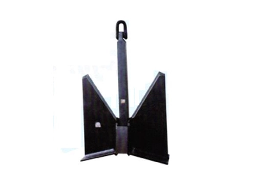
The stockless anchor is the standard bower anchor on the vast majority of commercial vessels worldwide. Its defining characteristic is the absence of a stock (the crossbar found on older anchor designs), which allows the anchor to be hauled directly into the hawsepipe for stowage — a critical practical advantage on commercial vessels where deck space is limited and rapid anchor handling is required.
How It Works:
The stockless anchor has a shank connected to a crown piece that carries two flukes. When the anchor lands on the seabed and the chain is tensioned, the crown piece pivots relative to the shank, driving the flukes into the seabed. The holding force is generated by the resistance of the seabed material to the flukes being dragged through it.
Performance Characteristics:
| Parameter | Characteristic |
|---|---|
| Holding power to weight ratio | Moderate (lower than high-holding-power designs) |
| Seabed penetration | Good in soft to medium seabeds |
| Performance in hard seabeds | Reduced — flukes may not penetrate |
| Self-launching | Excellent — drops cleanly from hawsepipe |
| Self-stowing | Excellent — hauls directly into hawsepipe |
| Reliability | Very high — simple, proven design |
Typical Applications:
Cargo ships, bulk carriers, and tankers — primary bower anchors
Container ships
General commercial shipping
Classification Society Requirement: Stockless anchors on classified vessels must meet the weight requirements specified in the classification society’s equipment number (EN) calculation. The EN is a composite number derived from vessel displacement, windage area, and other factors that determines the required anchor weight and chain size.
High-holding-power anchors are designed to generate significantly greater holding force per unit weight than standard stockless anchors. Classification societies define HHP anchors as those achieving at least twice the holding power of a standard stockless anchor of the same weight in standard test conditions.
Design Principle:
HHP anchors achieve their superior holding power through optimized fluke geometry — larger fluke area, steeper fluke angle, and improved penetration characteristics — that allows them to dig deeper into the seabed and resist extraction more effectively.
Common HHP Anchor Designs:
AC-14 Anchor
The AC-14 is the most widely used HHP anchor in commercial shipping. Developed through systematic hydrodynamic and geotechnical research, it features a large fluke area and a fluke angle optimized for penetration in a wide range of seabed types.
Holding power: approximately 2–3 times standard stockless
Compatible with standard hawsepipe stowage
Approved by all major classification societies as HHP
Spek Anchor
The Spek anchor features a distinctive design with a movable crown piece and large flukes. It performs well in soft seabeds and is widely used on vessels operating in areas with soft mud or sand bottoms.
Pool Anchor
The Pool anchor is a high-holding-power design commonly used on offshore vessels and in applications where superior holding performance is required.
Advantages Over Standard Stockless:
Higher holding power allows use of a lighter anchor for equivalent holding force
Better performance in soft seabeds where standard stockless anchors may drag
Reduced anchor weight can improve vessel stability and reduce windlass load
Typical Applications:
Vessels operating in areas with soft or difficult seabeds
Offshore support vessels
Vessels where anchor weight reduction is beneficial
Any application where superior holding performance is required
Super high-holding-power anchors represent the highest performance category, achieving four or more times the holding power of a standard stockless anchor of equivalent weight. They are used in specialized applications where maximum holding force is required.
Typical Applications:
Offshore mooring systems
Vessels operating in extreme weather regions
Specialized anchoring applications where standard HHP performance is insufficient
The Admiralty pattern anchor — the classic anchor shape familiar from maritime iconography — features a long stock perpendicular to the flukes that ensures the anchor lands in the correct orientation for the flukes to engage the seabed.
Performance Characteristics:
Excellent holding power in rocky and hard seabeds
Reliable engagement across diverse seabed types
Cannot be stowed in a hawsepipe — requires deck stowage
Limitations:
Deck stowage requirement makes it impractical for most commercial vessels
Handling is more complex than stockless designs
Typical Applications:
Small craft and yachts
Vessels where deck stowage is acceptable
Historical and traditional vessel applications
The mushroom anchor has a distinctive inverted dome shape that embeds progressively into soft seabed material over time, developing very high holding force through suction and burial.
Performance Characteristics:
Excellent long-term holding in soft mud and silt
Holding force increases with time as anchor embeds deeper
Not suitable for rocky or hard seabeds
Cannot be quickly reset if dragged
Typical Applications:
Permanent or semi-permanent moorings
Buoy moorings
Lightship and navigation buoy anchoring
Applications where the anchor will remain in place for extended periods
Drag embedment anchors are specialized high-performance anchors used in offshore mooring systems. They are designed to be dragged along the seabed under high tension, embedding progressively deeper until they reach their design holding capacity.
Common Types:
Vryhof Stevpris
Bruce anchor
Flipper Delta
Performance Characteristics:
Very high holding power to weight ratio
Designed for permanent or semi-permanent offshore mooring
Requires significant drag distance to reach full holding capacity
Not suitable for conventional vessel anchoring operations
Typical Applications:
Offshore platform mooring systems
FPSO mooring
Semi-submersible mooring
Anchor leg mooring (ALM) systems
Suction pile anchors (also called suction caissons) are large-diameter steel cylinders that are installed by pumping water out of the interior, creating a pressure differential that drives the pile into the seabed.
Performance Characteristics:
Extremely high holding capacity — suitable for the largest offshore structures
Precise installation positioning
Can be retrieved and reused in some applications
Requires specialized installation equipment
Typical Applications:
Deepwater offshore platform mooring
Subsea pipeline anchoring
Offshore wind foundation systems
| Anchor Type | Holding Power | Seabed Suitability | Stowage | Primary Application |
|---|---|---|---|---|
| Stockless | Standard | Sand, mud, gravel | Hawsepipe | Commercial shipping (bower) |
| HHP (AC-14, Spek) | 2–3× standard | Sand, mud, soft | Hawsepipe | Commercial shipping, offshore |
| SHHP | 4×+ standard | Variable | Hawsepipe | Specialized offshore |
| Admiralty pattern | High | Rock, hard, variable | Deck only | Small craft, traditional |
| Mushroom | Very high (long-term) | Soft mud, silt | Permanent | Permanent moorings, buoys |
| Drag embedment | Very high | Sand, clay | Offshore deployment | Offshore mooring systems |
| Suction pile | Extreme | Soft to medium | Offshore installation | Deepwater offshore structures |
The anchor chain is as critical to anchoring system performance as the anchor itself. An undersized, incorrect grade, or poorly maintained chain is a single point of failure in the anchoring system.
Anchor chain is classified by grade, which reflects the steel’s tensile strength and the chain’s minimum breaking load (MBL) relative to its nominal diameter.
| Grade | Designation | Relative Strength | Typical Application |
|---|---|---|---|
| Grade 1 (Q1) | Mild steel | Baseline | Older vessels; light duty |
| Grade 2 (Q2) | Higher strength | ~1.4× Grade 1 | General commercial shipping |
| Grade 3 (Q3) | High strength | ~2.0× Grade 1 | Modern commercial vessels |
| Grade 4 (Q4) | Extra high strength | ~2.5× Grade 1 | Offshore mooring; demanding applications |
Most modern commercial vessels use Grade 3 (Q3) chain, which provides the best balance of strength, weight, and cost for standard anchoring applications. Grade 4 chain is used where maximum strength with minimum weight is required.
Stud Link Chain
Stud link chain has a stud (crossbar) welded or cast across the interior of each link. The stud prevents the link from deforming under load and reduces the risk of kinking.
Standard for commercial vessel bower anchors
Required by classification societies for vessels above a certain size
Provides consistent geometry for windlass wildcat engagement
Open Link Chain (Kenter Chain)
Open link chain without studs is lighter and more flexible but has lower strength for a given diameter. Used in some mooring applications and on smaller vessels.
Classification society rules require that anchor chain be supplied with a certificate of conformity documenting:
Steel grade and heat treatment
Mechanical test results (tensile strength, elongation, impact toughness)
Proof load test results
Dimensional inspection results
Manufacturer identification
Chain without valid certificates should not be accepted for use on classified vessels. Traceability of chain material is essential for maintaining classification society approval.
Each shot (length) of anchor chain must be marked to identify its grade and position in the chain locker. Standard marking systems use paint, wire, or swivel links at defined intervals to indicate the amount of chain deployed during anchoring operations.
Determining the required anchor holding power is an engineering calculation, not a rule of thumb. Undersizing the anchoring system creates unacceptable risk; oversizing increases cost and weight unnecessarily.
Environmental Loads:
Wind force on the vessel’s hull and superstructure (function of wind speed and windage area)
Current drag on the hull and underwater appendages
Wave-induced surge forces
Vessel Characteristics:
Displacement
Windage area (projected lateral area above waterline)
Underwater hull form
Anchoring Arrangement:
Single anchor vs. multiple anchor arrangement
Chain scope
Water depth
For preliminary design purposes, the required anchor holding force can be estimated from:
Wind Force:
F_wind = 0.5 × ρ_air × C_d × A × V²
Where:
ρ_air = air density (approximately 1.225 kg/m³)
C_d = drag coefficient (typically 1.0–1.3 for ship hulls)
A = projected windage area (m²)
V = design wind speed (m/s)
Current Force:
F_current = 0.5 × ρ_water × C_d × A_underwater × V_current²
The total required holding force is the vector sum of wind and current forces, accounting for their relative directions.
For classified vessels, the required anchor weight and chain size are determined by the Equipment Number (EN), calculated according to the classification society’s rules:
EN = Δ^(2/3) + 2 × B × d + A/10
Where:
Δ = vessel displacement (tonnes)
B = vessel breadth (m)
d = vessel depth to freeboard deck (m)
A = projected lateral area of hull and superstructure above waterline (m²)
The EN is used to enter the classification society’s equipment table, which specifies the required anchor weight, chain diameter, chain grade, and chain length.
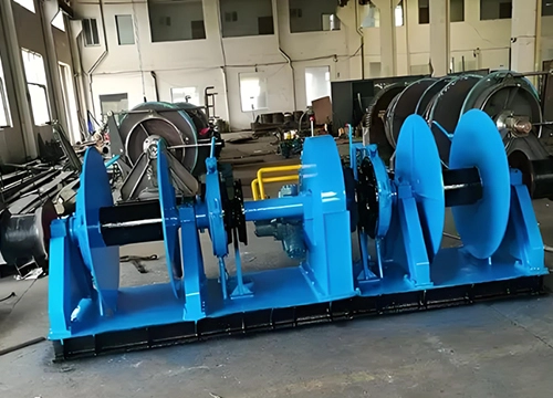
The windlass is the deck machinery responsible for deploying and recovering the anchor and chain. It is a safety-critical system — a windlass that fails to hold the chain under load, or that cannot recover the anchor in deteriorating weather, creates an immediate operational emergency.
Horizontal Windlass
In a horizontal windlass, the wildcat (the sprocket wheel that engages the chain) rotates on a horizontal axis. The chain runs horizontally across the wildcat before dropping into the chain locker.
Advantages:
Lower profile — suitable for vessels with limited freeboard
Good visibility of chain during operation
Widely used on smaller commercial vessels and yachts
Limitations:
Chain routing requires careful design to avoid sharp bends
Less suitable for very large chain sizes
Vertical Windlass (Windlass with Vertical Wildcat)
In a vertical windlass, the wildcat rotates on a vertical axis. The chain drops vertically from the wildcat into the chain locker below deck.
Advantages:
Compact deck footprint
Efficient chain routing — chain drops directly into locker
Preferred for large commercial vessels with heavy chain
Limitations:
Higher profile than horizontal designs
Motor and gearbox typically below deck — requires watertight arrangement
Combined Windlass-Mooring Winch
Many commercial vessels use combined units that incorporate both the anchor windlass and mooring winches in a single deck machinery arrangement, reducing the number of separate units and simplifying the deck layout.
Electric Drive
Electric windlasses use an electric motor (AC or DC) driving the wildcat through a gearbox. They are the most common drive system on modern commercial vessels.
Advantages:
Clean, controllable power
Easy speed control
Compatible with vessel’s electrical system
Low maintenance compared to hydraulic systems
Limitations:
High starting current demand — requires adequate electrical supply
Motor protection required against overload and water ingress
Hydraulic Drive
Hydraulic windlasses use a hydraulic motor driven by the vessel’s hydraulic power unit (HPU) or a dedicated hydraulic pump.
Advantages:
High torque at low speed — ideal for heavy chain recovery
Smooth, stepless speed control
Compact motor size for given torque output
Overload protection through pressure relief valve
Limitations:
Requires hydraulic power unit
Hydraulic oil leakage risk
More complex maintenance than electric systems
Electro-Hydraulic Drive
Electro-hydraulic systems combine an electric motor driving a dedicated hydraulic pump, which in turn drives a hydraulic windlass motor. This arrangement provides the control advantages of electric drive with the torque characteristics of hydraulic operation.
Rated Pull (Nominal Pull)
The continuous pulling force the windlass can exert at rated speed. This must be sufficient to recover the anchor and chain under the worst expected conditions — typically defined as recovering the full chain length at maximum scope in the design current and wind conditions.
Maximum Pull (Stall Pull)
The maximum force the windlass can exert at zero speed. This is typically 1.5–2.0 times the rated pull and represents the windlass’s ability to break out an anchor that has become deeply embedded.
Chain Speed
The rate at which chain is recovered, typically expressed in meters per minute. Classification society rules specify minimum chain speeds for commercial vessels.
Brake Holding Capacity
The maximum load the windlass brake can hold without slipping. This is a critical safety parameter — the brake must be capable of holding the full static load of the deployed chain plus the dynamic loads imposed by vessel motion in the design sea state.
Classification society rules typically require the brake to hold a load of at least 80% of the chain’s minimum breaking load (MBL).
Wildcat Design
The wildcat must be correctly designed for the chain grade and diameter being used. Incorrect wildcat geometry results in poor chain engagement, accelerated wear, and risk of chain jumping off the wildcat under load.
Windlass sizing should be based on a systematic calculation of the loads the system must handle:
Step 1: Determine Chain Weight
Calculate the total weight of chain to be deployed (chain length × weight per meter for the specified grade and diameter).
Step 2: Calculate Catenary Load
Determine the tension in the chain at the hawsepipe for the design anchoring condition (water depth, scope, environmental loads).
Step 3: Add Dynamic Loads
Apply a dynamic load factor to account for vessel motion and wave-induced surge.
Step 4: Select Windlass Rated Pull
The windlass rated pull must exceed the calculated chain tension with an appropriate safety margin.
Step 5: Verify Brake Capacity
Confirm that the brake holding capacity meets or exceeds the classification society requirement (typically 80% of chain MBL).
Classification society rules for anchoring systems are comprehensive and mandatory for all classed vessels. Key requirements cover:
As described above, the EN determines the required anchor weight, chain diameter, chain grade, and chain length. Vessels must carry anchors and chain that meet or exceed the EN requirements.
Classification rules specify:
Minimum rated pull based on chain size and vessel type
Minimum brake holding capacity (typically 80% of chain MBL)
Minimum chain recovery speed
Motor protection requirements
Control system requirements
Emergency stop provisions
Minimum volume to accommodate the required chain length
Drainage arrangements
Access for inspection and maintenance
Chain stopper requirements
Classification societies require periodic surveys of anchoring system components:
Annual survey: Visual inspection of windlass, chain, and anchor; verification of brake function
Special survey (every 5 years): Detailed inspection including chain measurement, windlass overhaul, and anchor inspection
Visual Inspection (Each Use / Annually):
Inspect all surfaces for cracks, particularly at the shank-crown junction and fluke roots
Check fluke pivot pins and securing arrangements
Inspect anchor shackle — verify pin is correctly moused
Check coating condition — repair bare metal areas promptly
Verify anchor weight marking is legible
Dry-Dock Inspection:
Full dimensional survey — compare against original specifications
Non-destructive testing (NDT) of high-stress areas
Fluke pivot mechanism inspection and lubrication
Full recoating if required
Chain wear is the primary cause of chain degradation. As chain links wear at their contact points, the link diameter reduces and the chain’s strength decreases. Classification society rules specify the maximum permissible wear before chain must be replaced.
Typical Wear Limit: Chain must be replaced when link diameter has worn to 87% of the nominal diameter (i.e., maximum wear of 13% of original diameter).
Chain Inspection Procedures:
Visual Inspection (Annual):
Inspect for cracked, bent, or deformed links
Check stud condition — loose or missing studs indicate overloading or fatigue
Inspect joining shackles (Kenter shackles) — verify lead plugs are intact
Check chain markings — verify position markings are legible
Dimensional Measurement (Special Survey):
Measure link diameter at wear points — compare against wear limit
Measure link length — elongation indicates overloading
Document measurements for trend analysis
Chain Cleaning:
Remove marine growth and corrosion products
Apply corrosion-inhibiting treatment to cleaned chain
Inspect coating condition in chain locker
Routine Maintenance (Monthly):
Lubricate all grease points per manufacturer’s schedule
Check brake lining condition and adjustment
Test brake holding capacity — verify chain does not slip under load
Inspect wildcat for wear — check chain engagement
Check hydraulic oil level and condition (hydraulic systems)
Test emergency stop function
Inspect electrical connections and motor protection (electric systems)
Annual Maintenance:
Full inspection of gearbox — check oil level and condition; inspect for leaks
Brake lining measurement — replace if worn beyond manufacturer’s limit
Wildcat wear measurement — replace if worn beyond classification tolerance
Motor insulation resistance test (electric systems)
Hydraulic system pressure test (hydraulic systems)
Full operational test under load
Common Windlass Failure Modes:
| Failure Mode | Cause | Prevention |
|---|---|---|
| Brake slip under load | Worn brake linings; oil contamination of brake surface | Regular lining inspection; keep brake surfaces clean |
| Wildcat chain jump | Worn wildcat; incorrect chain grade | Regular wildcat measurement; verify chain-wildcat compatibility |
| Gearbox failure | Inadequate lubrication; overloading | Regular oil changes; avoid shock loading |
| Motor overload (electric) | Undersized motor; excessive chain load | Correct sizing; motor protection relay |
| Hydraulic leak | Seal wear; hose damage | Regular seal inspection; hose replacement schedule |
Anchoring in sensitive marine environments — coral reefs, seagrass beds, and protected marine areas — can cause significant ecological damage. Many port authorities and marine protected area (MPA) managers now prohibit anchoring in sensitive areas or require the use of designated anchoring zones.
Vessel operators should:
Consult nautical charts and port authority notices for anchoring restrictions
Use mooring buoys where provided in sensitive areas
Avoid anchoring in areas with visible coral or seagrass
Anchor chains stored in chain lockers are subject to accelerated corrosion from trapped seawater and biological activity. Regular chain locker cleaning, drainage maintenance, and application of corrosion-inhibiting treatments significantly extend chain service life.
GPS-based anchor watch systems that alert the bridge team when the vessel moves beyond a defined radius are now standard on most commercial vessels. More sophisticated systems integrate GPS position data with wind, current, and chain tension data to provide early warning of anchor drag before the vessel has moved significantly.
IoT-enabled windlass monitoring systems that track motor current, brake temperature, hydraulic pressure, and chain tension in real time are enabling predictive maintenance approaches that reduce unplanned failures and extend equipment service life.
Development of Grade 4 and experimental Grade 5 chain materials is enabling anchoring systems with significantly reduced chain weight for equivalent holding capacity — an important consideration for vessels where topside weight is a constraint.
Research into autonomous anchoring systems — where the vessel’s navigation system automatically selects the optimal anchoring position, deploys the correct scope, and monitors holding performance — is progressing, driven by the broader trend toward autonomous vessel operations.
The marine anchoring system — anchor, chain, and windlass — is a safety-critical assembly that must be correctly specified, properly installed, and diligently maintained to perform reliably when it is needed most.
The key principles for ensuring anchoring system reliability are:
Select the correct anchor type for the seabed conditions — stockless and HHP anchors for standard commercial operations; specialized designs for offshore and permanent mooring applications
Size the system correctly — use the classification society’s Equipment Number calculation, not rules of thumb
Specify the correct chain grade — Grade 3 for most commercial applications; Grade 4 where weight reduction is critical
Size the windlass for the actual loads — rated pull, brake capacity, and chain speed must all be verified against calculated requirements
Implement a structured inspection program — chain wear measurement, brake lining inspection, and windlass maintenance are not optional
Comply with classification society requirements — annual and special survey requirements exist because anchoring system failures have real consequences
For shipowners, naval architects, and marine engineers, the anchoring system deserves the same rigorous engineering attention as the propulsion system or the mooring arrangement. A vessel that cannot anchor safely is a vessel that cannot operate safely.
A stockless anchor is the standard bower anchor used on most commercial vessels. It provides reliable holding performance and can be stowed directly in the hawsepipe. A high-holding-power (HHP) anchor is designed to generate at least twice the holding force of a standard stockless anchor of the same weight, through optimized fluke geometry that allows deeper seabed penetration. HHP anchors are used where superior holding performance is required or where anchor weight reduction is beneficial.
Required anchor weight is determined by the classification society’s Equipment Number (EN) calculation, which accounts for vessel displacement, breadth, depth, and windage area. The EN is used to enter the classification society’s equipment table, which specifies the minimum anchor weight, chain diameter, chain grade, and chain length. This calculation is mandatory for all classed vessels.
Classification society rules typically require the windlass brake to be capable of holding a load of at least 80% of the anchor chain’s minimum breaking load (MBL). This ensures the brake can hold the chain under the maximum expected static and dynamic loads without slipping.
Visual inspection should be conducted annually and after any incident involving heavy anchoring loads or suspected overloading. Dimensional measurement of link diameter — to check against the wear limit of 87% of nominal diameter — should be performed at each special survey (every 5 years) or more frequently if the chain is operating in demanding conditions.
Anchor drag is most commonly caused by insufficient scope (chain length relative to water depth), incorrect anchor type for the seabed conditions, anchor weight below the required minimum, or sudden increases in environmental loads beyond the design condition. Prevention involves deploying adequate scope (minimum 5:1 in moderate conditions; 7:1 or more in severe weather), selecting the correct anchor type for the seabed, and ensuring the anchor system meets classification society requirements for the vessel.
An electric windlass uses an electric motor driving the wildcat through a gearbox. It is clean, controllable, and compatible with the vessel’s electrical system, but requires adequate electrical supply capacity. A hydraulic windlass uses a hydraulic motor driven by a hydraulic power unit, providing high torque at low speed and smooth stepless control, but requires a hydraulic system and carries oil leakage risk. Electro-hydraulic systems combine both technologies, using an electric motor to drive a dedicated hydraulic pump.
Normanship supplies marine deck machinery, anchoring equipment, and mooring systems for commercial shipping, offshore operations, and shipbuilding projects. Contact our technical team for guidance on anchor and windlass specifications, classification society requirements, and certified marine deck equipment.


 English